|
|
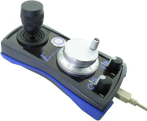
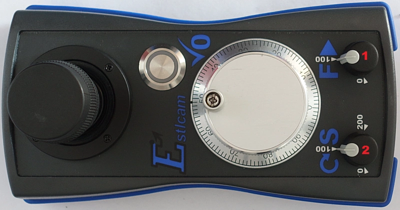
Estlcam CNC Handwheel pendant
- Joystick X/Y/Z:
- Simultaneous movement of all axes possible (Z-axis by turning the stick)...
- Very sensitive from slowest crawl up to maximum speed...
- Handwheel:
- Very fine und controlled movements...
- Instantaneous, direct coupling to the axis:
Never to fast, never overshoots the target...
- Axis selection is done automatically according to the joysticks last movement.
Intuitive control without need to press buttons all the time...
- Feed und Speed override by turning the knobs...
- Program und spindle start / stop by pressing the knobs...
- Set axis zero with the button in the middle...
- Suitable for:
- Dimensions: about. 185 x 100 x 95mm...
I only sell this product in Germany - sorry...
But the hardware design is freely available for reproduction!
|
 |
Connection:
- The Estlcam CNC handwheel pendant is connected by a Mini-DIN cable to the according connectors on the Terminal Adapter or LPT / Parallel Port Adapter.
- Make sure the cable is inserted completely into the connector - it sometimes needs a little push...
Configuration:
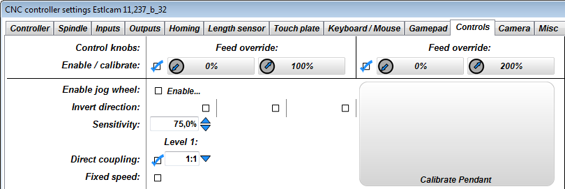
- Go to the "Controls" tab in the CNC controller configuration window...
- Klick the large "Calibrate pendant..." button und follow the instructions...
- There are some settings to adjust the pendant to your personal preferences...
Just have a look at the tooltips that appear when you rest the mouse over a field...
- As long as the setup window is open the pendant will not move the machine!
You need to close the window first to make the pendant work...
Use:
- The pendant basically takes care of 2 operations:
- Moving the machine / setting up a workpiece:
- The main work is done by the joystick - it allows to quickly move the machine to any location.
- By default the joystick can move all 3 axes at once - if you don't like this you can enable "single axis mode" in the setup window...
- The handwheel is mainly for precisely touching off workpieces / setting workpiece zero:
- First use the joystick to get close to the edge you want to touch off...
- Then use the handwheel for the last few mm...
- The handwheel always moves the axis that was last moved by the joystick - so its automatically the right one...
- Use the button in the center to zero the axis. Pressing shortly zeros the currently active axis, pressing longer zeros all axes...
- Control program flow:
- Pressing the "F" knob will start the CNC program...
- By turning the "F" knob you can adjust program speed from 0 to 100%...
- By turning the "S" knob you can adjust spindle RPM from 0 to 200%...
- If you press one of the 2 knobs while a CNC program is running the program will be paused...
Hardware design release Estlcam CNC handwheel pendant:
Production, sales and customer support for Estlcam hardware is taking up far too much time by now.
I want to be able to focus more on software development again which unfortunately slowed to a crawl over the last year.
Also I'm only shipping hardware within Germany and constantly have to turn down international customers.
So... I decided to release all Estlcam hardware designs for everyone to use...
No limit or warranty! Use at your own risk!
Conditions for personal use:
- There is one very important condition for personal use: It must not cost any of my time!
- Please don't be mad at me but questions regarding personal reproductions will usually not be answered - otherwise the result would be the complete opposite of saving time.
Conditions for commercial use:
- Commercial reproductions are allowed and even very welcome.
- Adaptions, further development or use for other projects even if not related to Estlcam are also OK.
- But I take no responsibility and no liability for the data or final product!
- Customer support for your products is your responsibility!
- Your product needs to be distinguishable from my own products! (Your product must at least have a well sticking label with your address.)
Downloads:
ISP Programming pads:
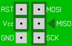
- The Atmega328PB either needs to be programmed before SMD assembly in a TQFP32 programming socket...
- Or after SMD assembly using the programming pads at the bottom side of the PCB:
- The programming pads make all pins available required by an STK500 compatible programmer...
- But the arrangement of the pads does not conform to the the usual 6-Pin ISP layout!
- Pin "MISO" is marked by a triangle to show correct alignment...
Build instructions...
Soldering Flexible PCB / Spacer_A / Mini-DIN Connector und Potentiometers:
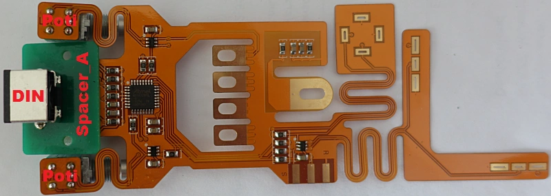 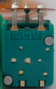
- Put the Mini-DIN connector on "Spacer_A"...
- Put both parts from above on the flexible PCB und solder them...
- Put the potentiometers from below on the flexible PCB und solder them...
- It is extremely important to solder those parts from the correct side as shown in the picture!
- The potentiometers are quite sensitive. They do not like too much heat over too long time und also dislike if you exert force on the pins!
Do not stick the potentiometers completely through the flexible PCB but just a little so they can be soldered - this minimizes the heat they have to endure.
If the potentiometer body gets too hot it will get soft und the internal switch may not work anymore...
Assembly Joystick, Button und handwheel
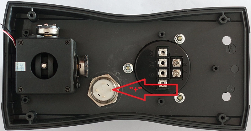 
- Assemble the parts as shown in the picture...
- Make absolutely sure the "+" marking of the button is on the right side as shown in the picture! This is extremely important - otherwise the button will not work!
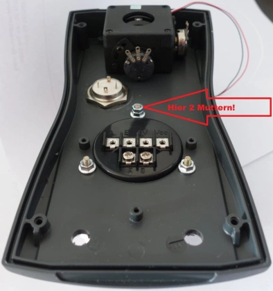
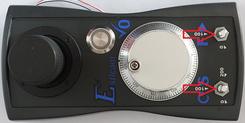
- The center handwheel screw is secured with 2 nuts as shown in the right picture: a flange nut und a regular one on top...
- The other 2 screws are only secured with one flange nut each...
- Make sure all parts are aligned as shown in the picture...
- The joystick screws are easy to damage if an unsuitabe or worn out screwdriver is used!
Assembly Spacer_B und Spacer_C
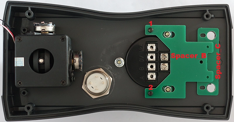
- Assemble Spacer "B" with 2 Screws 2,5x6mm (Picture Pos 1 und 2) as shown...
- Insert Spacer "C" loosely...
Assembly Flexible PCB
- Put the potentiometers through the holes of "Spacer_C" and the enclosure...
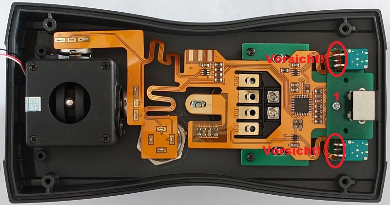
- Make sure not to press on the flexible PCB in the areas shown in the picture...
- Insert the screw 2,5x10mm (Picture Pos 1) loosely - but do not tighten yet...
- Align the flexible PCB nicely and put it on all pins...
Assembly Pressure_Plate
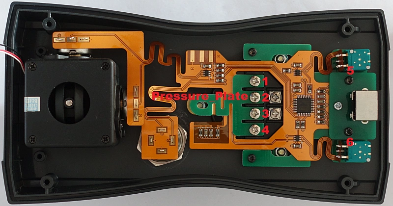 Assemble the part "Pressure_Plate" with 4 screws M3x6 - but do not tighten them yet. (Picture Pos 1 to 4)...
Insert 2 screws 2,5x6mm as shown in the picture - again just loosely (Picture Pos 5 and 6)...
Verify everything is nicely aligned, then tighten all loose screws...
Do not use too much force - the screws are small!
The part "Pressure_Plate" will bend - this is intentional...
Assemble the part "Pressure_Plate" with 4 screws M3x6 - but do not tighten them yet. (Picture Pos 1 to 4)...
Insert 2 screws 2,5x6mm as shown in the picture - again just loosely (Picture Pos 5 and 6)...
Verify everything is nicely aligned, then tighten all loose screws...
Do not use too much force - the screws are small!
The part "Pressure_Plate" will bend - this is intentional...
Soldering Button and Joystick:
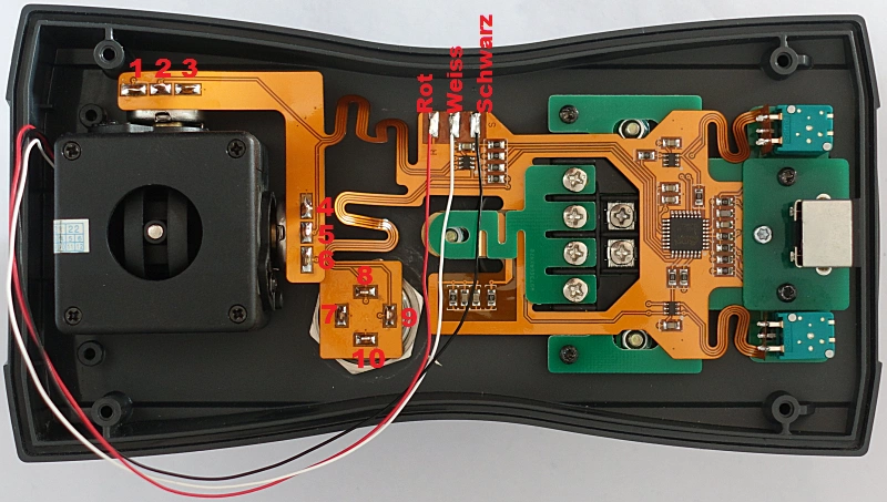
- Solder all contacts on Joystick an Button...
- Solder the red wire to the left contact pad...
- Solder the white wire to the center contact pad...
- Solder the black wire to the right contact pad...
Assemble Potentiometer Nuts:
- Make sure not to press on the flexible PCB on the back side - it may cause damage...
Prepare Enclosure lower part:
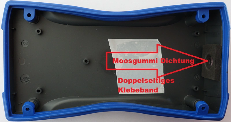
- Mount the protective seal...
- Stick the cellular rubber seal against the cable opening - it prevents chips and dirt from entering...
- Add a bit of double sided adhesive tape to the inside of the enclosure - it is there to catch any dirt that may still find its way into the enclosure and prevent it from causing short circuits...
Final assembly:
- Put the enclosure together - make sure the joystick wires do not get pinched somewhere...
- Put the knobs on the potentiometers...
- Finished...
|