|
|
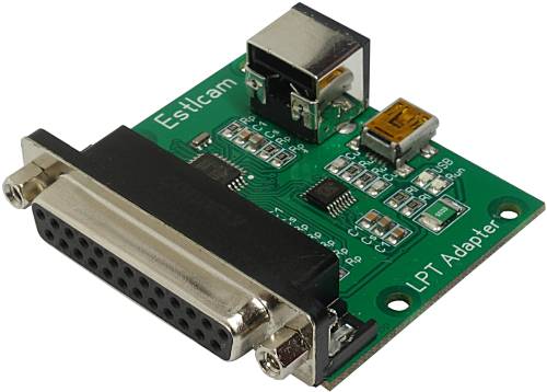
Estlcam LPT / Parallel Port Adapter
- USB CNC controller for Estlcam...
- Universal adapter for machines and stepper drivers with LPT / parallel port connectors...
- Connector pinout can be configured to be compatible with most stepper drivers and machines...
- Many presets available:
- Benezan Mini Breakout-Board
- BZT ST...
- CNC Plus SMS303
- CNC Profi KJ
- CNC-Step Zero 3
- GoCNC
- Langenfeld Parallel Interface
- Leadshine MX3660
- Letmathe MDLCNC
- Lewetz Step3s
- Mechaplus
- Mechapro Slider SFX
- OMC Stepperonline Breakout ST-V2
- Optimum CNC Controller IV
- Sorotec Interface Advanced Pro
- Stepcraft
- Triple Beast
- Connector for external modules:
I only sell this product in Germany - sorry...
But the hardware design is freely available for reproduction!
|
 |
Hardware design release Estlcam LPT / Parallel Port Adapter:
Production, sales and customer support for Estlcam hardware is taking up far too much time by now.
I want to be able to focus more on software development again which unfortunately slowed to a crawl over the last year.
Also I'm only shipping hardware within Germany and constantly have to turn down international customers.
So... I decided to release all Estlcam hardware designs for everyone to use...
No limit or warranty! Use at your own risk!
Conditions for personal use:
- There is one very important condition for personal use: It must not cost any of my time!
- Please don't be mad at me but questions regarding personal reproductions will usually not be answered - otherwise the result would be the complete opposite of saving time.
Conditions for commercial use:
- Commercial reproductions are allowed and even very welcome.
- Adaptions, further development or use for other projects even if not related to Estlcam are also OK.
- But I take no responsibility and no liability for the data or final product!
- Customer support for your products is your responsibility!
- Your product needs to be distinguishable from my own products! (Your product must at least have a well sticking label with your address.)
Downloads:
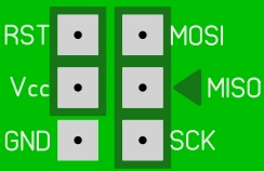
ISP Programming pads:
- The Atmega328PB either needs to be programmed before SMD assembly in a TQFP32 programming socket...
- Or after SMD assembly using the programming pads at the bottom side of the PCB:
- The programming pads make all pins available required by an STK500 compatible programmer...
- But the arrangement of the pads does not conform to the the usual 6-Pin ISP layout!
- Pin "MISO" is marked by a triangle to show correct alignment...
User manual:
Important:
- Please read first before starting to work...
- Install the most recent Estlcam version...
- Prevent short circuits and wrong polarity:
- Shorts and wrong polarity can damage the CNC controller, connected components and even your computer!
- Mount the adapter in a way that protects it from chips, liquids and dust...
- If mounting on metal make sure the PCB cannot touch the metal...
- Make sure all connections are tight and properly isolated.
- No frayed cable ends! Use cable-end sleeves...
- All changes should be made with power turned off and USB cable disconnected...
- Check everything carefully before you put the controller into operation...
- Be ready for some unwanted surprises during commissioning - e.g. a self starting spindle motor!
- Remove any tools from the spindle and keep your distance until everything works as intended...
- Use only high quality USB cables
- Cheap USB cables can cause the machine to stop unexpectedly...
Driver installation:
- If internet is available the driver is usually installed automatically...
- Alternatively you can download it here:
Connecting the adapter:
- Connect the adapter with your computer...
- Make sure to use a high quality USB cable (well shielded and not excessively long)...
- Cables with bad shielding often cause issues with USB connection losses in CNC machine environments...
- Connect the adapter with your stepper driver or machine:
- Either by using a 25 pin 1:1 parallel port cable
- Or by directly mounting it to the stepper drivers connector (after removing the interfering bolts from the adapter)...
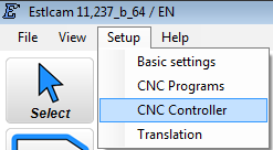
Configuration:
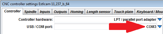
- Menu "Setup" -> "CNC Controller":
- Select "LPT parallel port adapter" in the "Controller hardware" list:
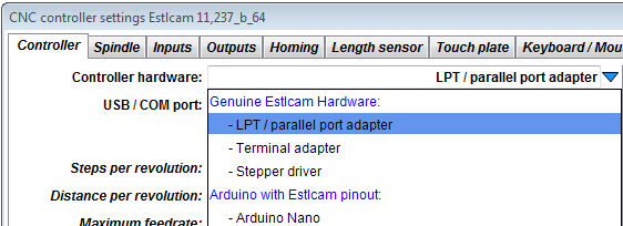
- Now this window appears:
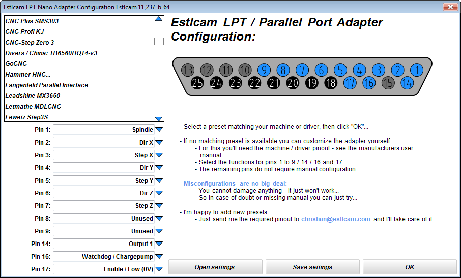
- Is there a suitable preset?
- Just select your machine or stepper driver from the list...
- Then click OK...
- No suitable preset?
- If no suitable preset is available you can configure the pins of the adapter yourself - see tips further below...
- For this you need to know the correct pinout (see user manual of the stepper driver or machine)...
- In case of issues you can send me an eMail...
- After clicking OK Estlcam returns to the previous window.
Select your adapters COM Port in the "USB / COM port" list:
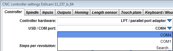
- If more than one port is available and you're not sure select "Search..." and follow the instructions...
- Finally fill out the remaining fields.
- Estlcam has extensive tooptips for each field - just let the mouse rest over it and it will appear...
- Finally click "Program controller" to program the adapter and start the controller...
Tips for manual adapter configuration:
- Pins 1 to 9, 14, 16 and 17 are output pins and can be configured individually.
- The functions "Dir X/Y/Z" and "Step X/Y/Z" can be used twice each if required (e.g. machines with 2 motors on the same axis)...
- Some stepper drivers expect an "enable" signal - without this the machine won't do anything at all:
- This is especially tricky if no user manual is available and you have to guess...
- Even worse this signal comes in 3 different flavours: "Enable High" / "Enable Low" and "Enable Watchdog"...
- Without manual the only way to find out is by trial and error. Usually the signal is expected on Pin 1. Less common on Pins 14, 16 or 17 (2 to 9 would be very unusual)...
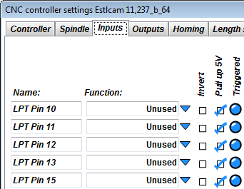
- Pins 18 to 25 are always ground pins - no configuration necessary...
- Pins 10 to 13 and 15 are inputs - they are not configured here but later in the "Inputs" tab of the controller setup dialog:
Increase communication speed:
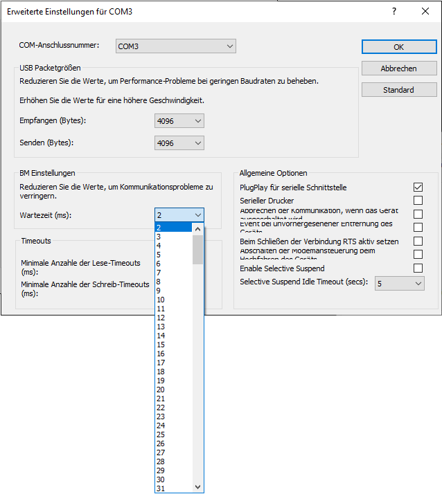
- By default the USB driver checks for new data from the controller every 16ms...
- This is OK in most cases but not perfect...
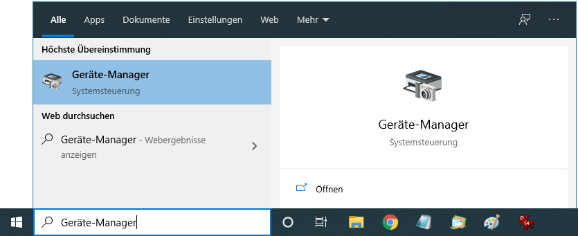
- To increase the responsiveness of the controller do this:
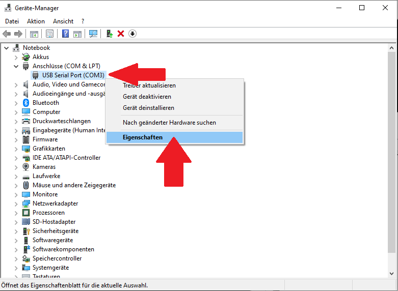
- Open the device manager (e.g. type "device manager" into the windows search bar):
- Check in Estlcam which "COM" Port is selected in the "USB COM port" list. In our case it is "COM3":
- Search for a "USB Serial Port" with this "COM" port number in the "Ports (COM & LPT)" section. In our case "USB Serial Port COM3"...
- Right-click this entry and select "Properties":
- Select the "Port Settings" tab and click "Advanced":

- Change the "Latency Timer (msec)" to 2ms:
|