|
|
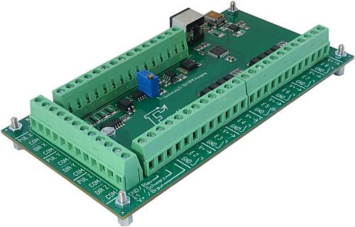
Estlcam Terminal Adapter
- USB CNC controller for Estlcam...
- Step and dir signals X/Y/Z for stepper drivers with screw terminals.
- e.g. Leadshine DM542 or JMC Servos..
- If required 2 stepper drivers can be connected to each axis...
- 8 Inputs for mechanical switches or NPN sensors...
- 4 Outputs for relays:
- 1x Spindle motor...
- 3x Additional functions (e.g. vacuum or lights)...
- VFDs can be connected directly:
- Start / stop by isolated optocoupler output...
- Spindle speed by 0-10V analog output...
- PWM Output...
- Connector for external modules:
- Required accessory:
- Power supply 12-24V depending on your relays and sensors accepted voltage range...
- Dimensions: 152,5x80mm / mounting holes distances: 142,5x70mm
I only sell this product in Germany - sorry...
But the hardware design is freely available for reproduction!
|
 |
Hardware design release Estlcam Terminal Adapter:
Production, sales and customer support for Estlcam hardware is taking up far too much time by now.
I want to be able to focus more on software development again which unfortunately slowed to a crawl over the last year.
Also I'm only shipping hardware within Germany and constantly have to turn down international customers.
So... I decided to release all Estlcam hardware designs for everyone to use...
No limit or warranty! Use at your own risk!
Conditions for personal use:
- There is one very important condition for personal use: It must not cost any of my time!
- Please don't be mad at me but questions regarding personal reproductions will usually not be answered - otherwise the result would be the complete opposite of saving time.
Conditions for commercial use:
- Commercial reproductions are allowed and even very welcome.
- Adaptions, further development or use for other projects even if not related to Estlcam are also OK.
- But I take no responsibility and no liability for the data or final product!
- Customer support for your products is your responsibility!
- Your product needs to be distinguishable from my own products! (Your product must at least have a well sticking label with your address.)
Downloads:
ISP Programming pads:
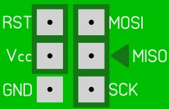
- The Atmega328PB either needs to be programmed before SMD assembly in a TQFP32 programming socket...
- Or after SMD assembly using the programming pads at the bottom side of the PCB:
- The programming pads make all pins available required by an STK500 compatible programmer...
- But the arrangement of the pads does not conform to the the usual 6-Pin ISP layout!
- Pin "MISO" is marked by a triangle to show correct alignment...
User manual:
Important:
- Please read first before starting to work...
- Install the most recent Estlcam version...
- Prevent short circuits and wrong polarity:
- Shorts and wrong polarity can damage the CNC controller, connected components and even your computer!
- Mount the adapter in a way that protects it from chips, liquids and dust...
- If mounting on metal make sure the PCB cannot touch the metal...
- Make sure all connections are tight and properly isolated.
- No frayed cable ends! Use cable-end sleeves...
- All changes should be made with power turned off and USB cable disconnected...
- Check everything carefully before you put the controller into operation...
- Be ready for some unwanted surprises during commissioning - e.g. a self starting spindle motor!
- Remove any tools from the spindle and keep your distance until everything works as intended...
- Use only high quality USB cables
- Cheap USB cables can cause the machine to stop unexpectedly...
Overview:
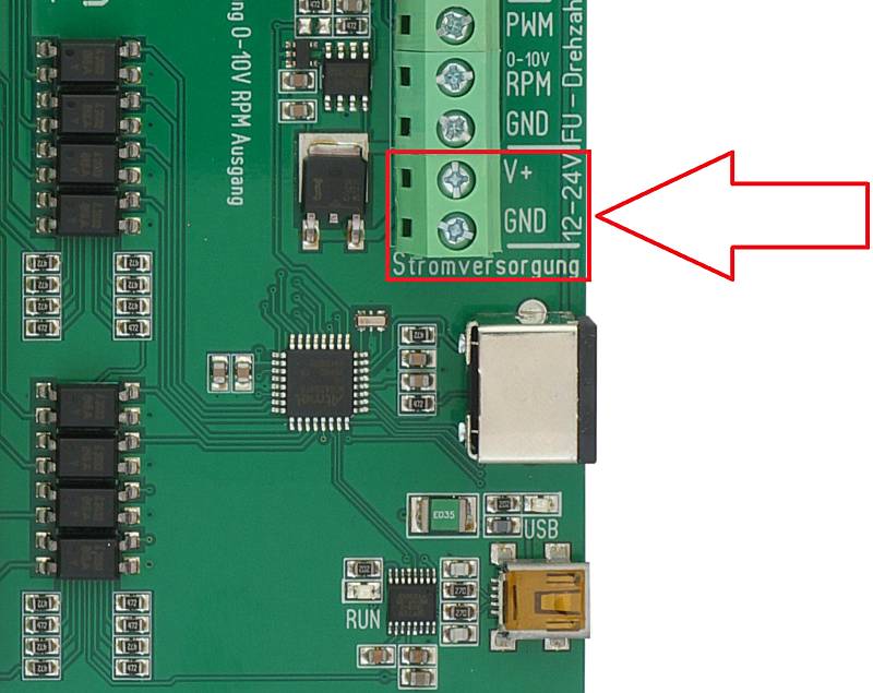
12 - 24V power supply:
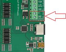 |
- The terminal adapter requires an external power supply between 12 and 24V to work correctly...
- The voltage primarily depends on the requirements of eventually used relays:
- If relays with 24V coil voltage are used use a 24V power supply...
- If relays with 12V coil voltage are used use a 12V power supply...
- In case of solid state relays with a wide range of accepted input voltages or if no relay is used I recommend 24V (industry standard)...
- Connect the power supplies positive output / "+" to "V+"...
- Connect the power supplies negative output / "-" to "GND" right next to it...
- Voltages above 30V destroy the adapter!
|
Connecting stepper drivers:
- The terminal adapter is intended to be used with stepper drivers with screw terminal connectors like e.g. Leadshine DM542...
- For each axis there are 4 terminals:
- PUL (X/Y/Z): Step signal for the axis...
- DIR (X/Y/Z): Direction signal for the axis...
- 2x "COM" for easy wiring:
- By default "COM" is connected to "GND" ("-" / negative terminal)...
- Optionally "COM" can be changed to "+5V" - see further below...
- All step and dir signals are 5V TTL signals and also work without external power supply...
- Prevent short circuits on the step and dir outputs - Risk of damage!
Leadshine and similar:
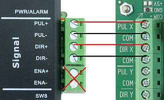 |
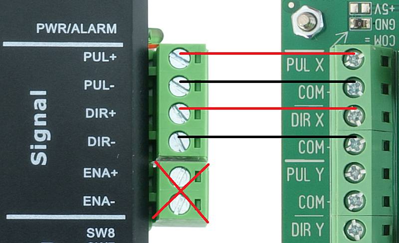
- Wiring of the stepper driver with the adapter:
- Connect "PUL+" (Step) of the driver with "PUL" of the adapter...
- Connect "DIR+" (Direction) of the driver with "DIR" of the adapter...
- Connect "PUL-" and "DIR-" with the adapters "COM" terminals...
- Ignore ENA+ and ENA-...
- Repeat for the Y and Z axis stepper drivers...
- If needed you can connect 2 stepper drivers for each axis:
- E.g. for machines with motors on both sides of the gantry portal...
- Just connect both drivers to the adapters corresponding terminals...
- Connecting more than 2 drivers on a single output may however cause damage due to excessive output currents!
|
JMC and similar with Alarm output:
 |
- Connecting the PUL and DIR signals for JMC servos and closed loop steppers works identical as shown above...
- Optionally the alarm signal can be connected to the adapter to shop the machine in case of position deviations or other errors:
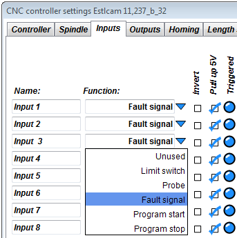
- Connect "ALM+" with any input of the adapter (E1 to E8)...
- Connect "ALM-" with "GND" right next to it...
- Configure the input as "Fault signal"...
- It is possible to connect several "ALM" signals to the same input of the terminal adapter to save inputs...
|
Stepper drivers with "Opto" connector / common anode:
 |
- There are more and more stepper drivers that instead of "PUL+" / "PUL-" / "DIR+" / "DIR-" have only 3 terminals "PUL" / "DIR" and "OPTO" instead...
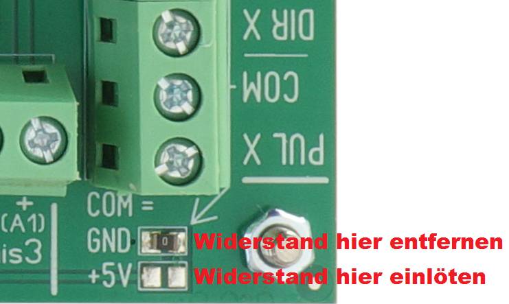
- To use them there is a little change necessary to switch the "COM" terminals from "GND" to "+5V":
- Remove the 0 ohm resistor from the "GND" field...
- And solder it onto the "+5V" field...
- If the resistor gets damaged or lost just connect the pads in the "+5V" fiel with solder...
- Now you can connect:
- "PUL" (Step) of the driver to "PUL" of the adapter...
- "DIR" (Direction) of the driver to "DIR" of the adapter...
- "OPTO" of the driver to one of the adapters "COM" terminals...
|
Tips for configuration:
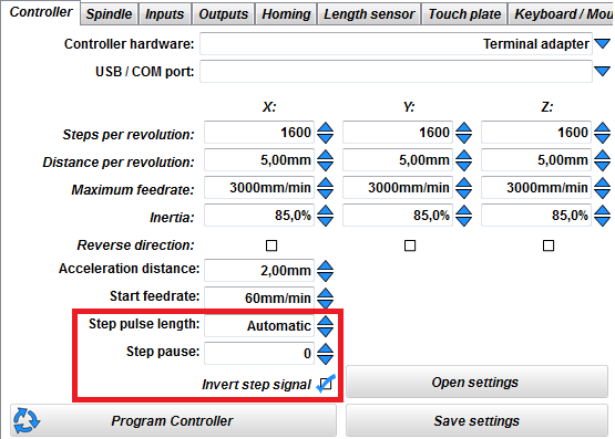 |
- For many stepper drivers it is recommended to check the "Invert step signal" box (e.g. most Leadshine and similar drivers):
- Those drivers read the dir signal at the rising edge of the step signal - but the dir signal may have changed just a very very short time before...
- It may happen that the driver internally still sees the old dir signal state and makes one step in the wrong direction. Over time this can add up to significant position errors...
- Inverting the step signal makes the dir signal change before the step signals falling instead of its rising edge - therefore dir changes can be seen by the driver much longer before the next step is executed...
- If you experience slowly increasing position errors changing the state of the "Invert step signal" checkbox is the first thing to try ...
- For stepper drivers that need even more time between changes on the dir signal and the next step you can increase the value in the "Step pause" field.
- This is however only necessary for a few drivers with exceptionally slow optocouplers on the dir signal...
- As this field affects running smoothness the values should remain 0 if possible...
- Some stepper drivers only work reliably with step impulses of a certain length.
- This can be adjusted in the "Step pulse length" field...
- Usually "Automatic" is the best setting - only a few drivers with very low step frequency limits are affected...
|
Inputs:
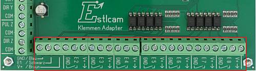
- The terminal adapter offers 8 inputs e.g. for
- Limit switches...
- Edge finders...
- Buttons...
- And other digital sensors and signals...
- Each input has 3 inputs to make wiring easy:
- "GND"...
- "E1" to "E8": as the actual input terminals...
- "V+": Power supply for electronic sensors:
Connecting mechanical switches and sensors:
- Connect one wire of the switch (no matter which one) with "GND"...
- And the other one with "E..."
- Ignore "V+"...
- You can use normally open and normally closed switches...
- You can connect several switches to the same input:
- In case of normally open as parallel circuit...
- In case of normally closed as series circuit...
- However: the purpose of the switches must be the same:
- You can e.g. combine several limit switches...
- But not e.g. a limit switch with a tool length sensor...
Connecting inductive proximity sensors / or NPN sensors in general:
- Connect the sensors blue wire with "GND"
- Connect the sensors black wire with "E..."
- Connect the sensors brown wire with "V+"
- Normally open or normally closed does not matter
- But it only works with sensors of the "NPN" type...
- In case of normally open sensors it is possible to combine several of them as parallel circuit and connect them to a single input to save inputs...
- Make sure the sensor is suitable for the choosen adapter supply voltage - see section 12 - 24V power supply.
But ususally this no issue except for very exotic things...
Connecting other sensors or signals:
- Each input is pulled up by a 5kOhm resistor to board supply voltage V+...
- It is switched by connecting it to "GND"...
- This can be done e.g. by mechanical switches, relay contacts or open collector outputs...
- Not compatible with tri-state / push-pull outputs (e.g. most microcontroller outputs)!
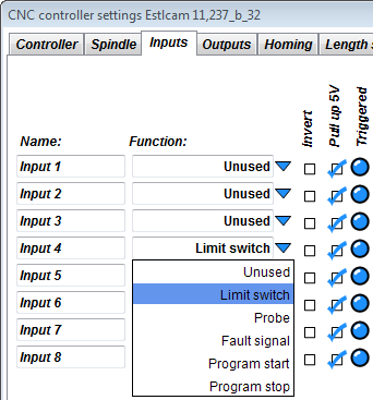
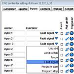
Input configuration:
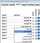 |
- To make the input perform the desired functionality you first need to configure it in the CNC controller setup dialog...
- Configuration however should wait until after initial commissioning is done!
Otherwise Estlcam may overwrite your settings with default values...
- Unused inputs should be configured as "unused"...
- In case of normally closed switches you need to check the "Invert" checkboxes!
|
Mini DIN connector for external modules:
 |
- The Mini-DIN connector is mainly intended for connection of external modules:
- But DIY solutions are also possible...
- More information about the Mini-DIN connector can be found here...
|
Connecting relays or solenoid valves:
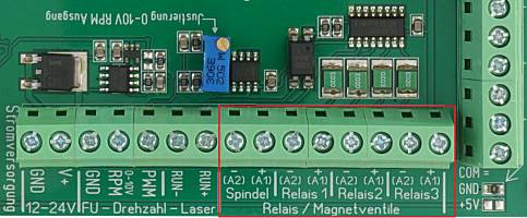
- The terminal adapter offers 4 outputs for relays or solenoid valves:
- "Spindle" for the spindle motor...
- "Relay 1 to 3" for other purposes like e.g. a vacuum cleaner or lights...
- Each output consists of a "+" and "-" terminal for easy wiring:
- The "+" terminal is directly connected to the adapters power supply...
- The "-" terminal is the actually switching output and closes to "GND" when activated...
- The terminals of the adapter cannot switch large currents (max 200mA)!
- You always need to put a relay between the adapter and any load!
- Make sure the relays coil voltage is matching the adapters power supply voltage -see section 12 - 24V power supply...
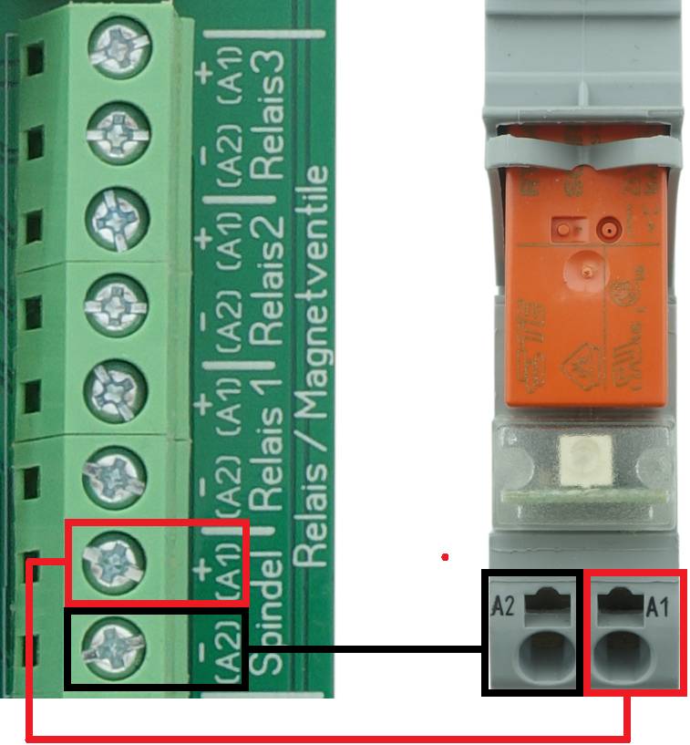
Connecting mechanical relays:
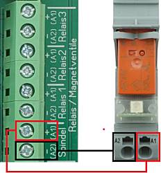
|
- Inexpensive solution, but may cause USB issues in rare cases...
- Many relays have internal free-wheeling diodes:
- If a relay with free-wheeling diode is connected with wrong polarity it will cause a short circuit!
The adapter has short circuit protection that works in most cases - but there is still a notable risk of major damage!
- If you're unsure whether there is a free-wheeling diode and which polarity is correct do not connect the relay to avoid damage!
- Connect "A1 (+)" of the relay with the "+" terminal of the desired adapter output...
- Connect "A2 (-)" of the relay with the "-" terminal of the desired adapter output...
- Make sure the relays coil voltage is matching the adapters power supply voltage see section 12 - 24V power supply
- Example of a relay that works well for most applications: Wago 788-304 24V
|
Connecting solenoid valves:
- Solenoid valves behave just like mechanical relays...
- You can use them e.g. for pneumatic clamping devices...
- But make sure coil current does not exceed 200mA!...
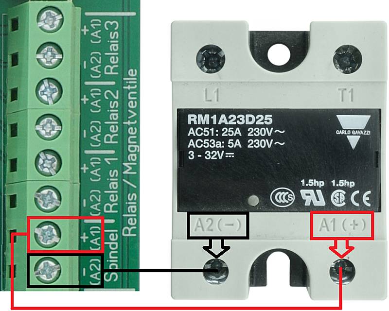
Connecting solid state relays (SSR):
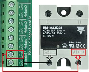
|
- SSR are quite expensive but switch with little interference and have no risky free-wheeling diodes...
- Connect "A1 (+)" of the relay with the "+" terminal of the desired adapter output...
- Connect "A2 (-)" of the relay with the "-" terminal of the desired adapter output...
- Make sure the relay has a zero crossing circuit - otherweise it may be destroyed by inductive loads like motors!
- Make sure the relay has a sufficient voltage and current rating - some need heat sinks to achieve the stated values!
- Make sure the relays input voltage range is matching the adapters power supply voltage siehe 12 bis 24V Spannungsversorgung
(This is however usually not an issue).
Example of a relay that works well for most applications: Carlo Gavazzi RM1A23D25
|
Connecting VFDs:
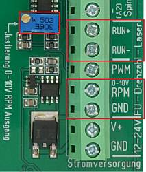 |
- The terminal adapter is able to control most VFDs directly:
- The terminals "RUN+" and "RUN-" provide an isolated switching output (open collector optocoupler output) that can be used to operate the VFDs "Run" input...
- The terminals "RPM" and "GND" provide a 0-10V analog rpm signal...
- Calibrate the RPM output first - see below!
- Terminal names of VFDs vary from manufacturer to manufacturer - you'll have to consult the user manual to find out what is what...
- Almost all VFDs are by default configured to be operated from their own control panel and ignore external run und rpm signals!
- You'll have to change the VFDs internal parameters accordingly which again requires consulting the user manual...
|
Examples (no guarantee / at your own risk!):
Huanyang Hy... Series:
- "RUN+" -> "FOR"
- "RUN-" -> "DCM"
- "RPM" -> "VI"
- "GND" -> "ACM"
- Parameter 1: "1"
- Parameter 2: "1"
- Parameter 72: "400"
- Parameter 73: "100"
- In case of control panel with potentiometer: change internal jumper from "VR" to "VI"...
"YL620":
- "RUN+" -> "FWD"
- "RUN-" -> "XGND"
- "RPM" -> "VI1"
- "GND" -> "GND"
- Parameter 00.01: "1"
0-10V RPM Output Calibration:
 |
- For calibration the adapter needs to be supplied with power and basic configuration and commissioning should already be completed...
- The VFD itself however should NOT be connected at this stage!
- Start the controller...
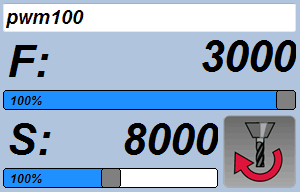
- Type "pwm100" in the controllers command line and press "Enter" key.
- The spindle symbol (picture right bottom) needs to change from blue to red...
- Measure the voltage between "RPM" and "GND".
- Make sure the terminal screws are tight. Loose screws often have bad contact and can result in wrong measurements...
- Turn the screw of the blue potentiometer until the voltage is about 9V (intentionally less than 10V)...
- Now close Estlcam, unplug power and USB cable...
- Connect the VFD...
- Reconnect USB and power, then start Estlcam again...
- Type "pwm100" into the command line once more and press "Enter" key...
- The spindle should now run with a little less than maximum speed...
- Turn the potentiometer screw until the spindle reaches max rpm, then turn a little more (1/4 turn)...
- Finished...
|
Connecting the adapter:
- Connect the adapter with your computer...
- Make sure to use a high quality USB cable (well shielded and not excessively long)...
- Cables with bad shielding often cause issues with USB connection losses in CNC machine environments...
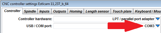
Configuration:
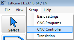
- Menu "Setup" -> "CNC Controller":
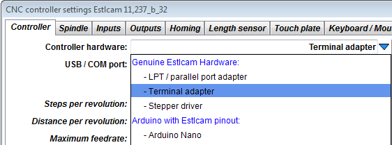
- Select "Terminal adapter" in the "Controller hardware" list:
Select your adapters COM Port in the "USB / COM port" list:
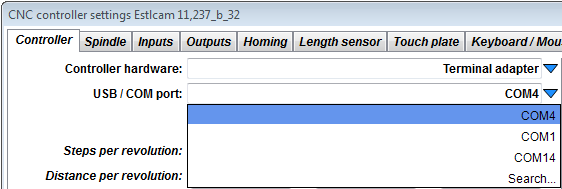
- If more than one port is available and you're not sure select "Search..." and follow the instructions...
- Finally fill out the remaining fields.
- Estlcam has extensive tooptips for each field - just let the mouse rest over it and it will appear...
- Finally click "Program controller" to program the adapter and start the controller...
Increase communication speed:
- By default the USB driver checks for new data from the controller every 16ms...
- This is OK in most cases but not perfect...
- To increase the responsiveness of the controller do this:
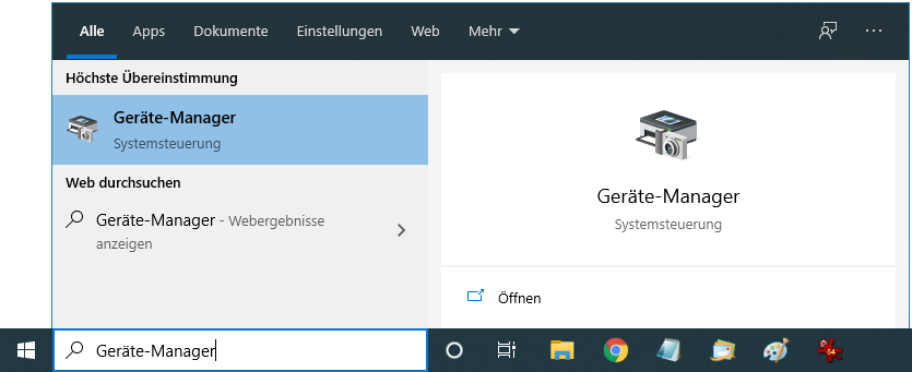
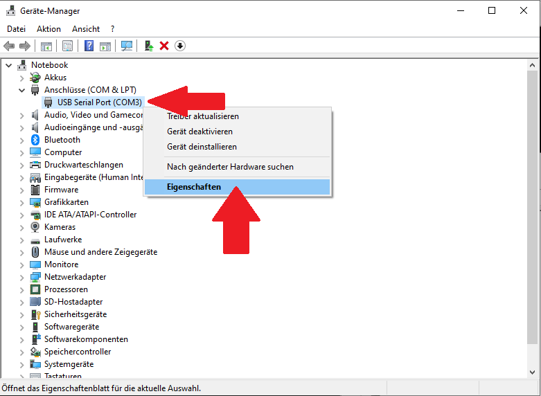
- Open the device manager (e.g. type "device manager" into the windows search bar):
- Check in Estlcam which "COM" Port is selected in the "USB COM port" list. In our case it is "COM3":
- Search for a "USB Serial Port" with this "COM" port number in the "Ports (COM & LPT)" section. In our case "USB Serial Port COM3"...
- Right-click this entry and select "Properties":
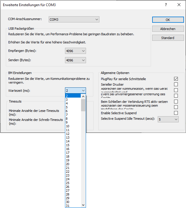
- Select the "Port Settings" tab and click "Advanced":

- Change the "Latency Timer (msec)" to 2ms:
|